Tag Archives: CHIP

Tiny Tapeout 8

Tiny Tapeout is an educational project that makes it easier and cheaper than ever to get your designs manufactured on a real chip! Instead of paying 10,000 dollars for taping out a chip, enthusiasts and hobbyists can submit designs and share the floorplans in the same chips, dramatically reducing the per-design cost for individuals.

The final chip product shipped to me will include a chip on a carrier board and a demo board to communicate with the chip.

Since I have completed ChipCraft‘s 8-bit calculator course (Slide 157 Lab ID: C-EQUALS), I decided to submit this design to the Tiny Tapeout 8th iteration (TT8), which is due on September 6, 2024.

Because my design is coded with TL-Verilog, I followed Steve Hoover‘s tt08-makerchip-template and the 5-minute YouTube tutorial, which are extremely helpful.

My submitted TT8 design can be found at ezchips/tt08-my-calc (github.com) repository.

During the process of compiling my design, I did run into GDS Build issue with the following error:

/home/runner/work/tt08-my-proj/tt08-my-proj/src/project.sv:124: ERROR: Identifier `\L1_Digit[0].L2_Leds[0].L2_viz_lit_a0' is implicitly declared and `default_nettype is set to none.

Steve provided me with a neat trick by adding `default_nettype wire to the first \SV region of the project.tlv file, and it worked beautifully.

Here is the snapshot of a successful submission reported by TT08’s discord group:

It is really cool to have a 2D and 3D view of my design’s floor plan in the chip, which includes many semiconductor components like gates, flip-flops, multiplexers, etc.

ChipCraft: Fibonacci and D Flip-Flop

The fibonacci sequence is a sequence of numbers where the first two terms are both 1 and the next terms are the sum of the two previous terms. In order to output the terms of this sequence using TL-Verilog, you need to be able to access previous cycles of numbers. This is where the “>>” operation comes in. 

In TL-Verilog, >> indicates that you want the value of some previous cycle of a variable. The storage of values from previous cycle is realized through the “D Flip-Flop“, the square block with a small triangle in it. For example, if you set something equal to >>3$num, the value will be the value of num three cycles before. With this operation in mind, it seems fairly trivial to come up with the code for the fibonacci sequence. The line of code

$num[31:0] = >>1$num + >>2$num;

seems to be enough. What this line means is that the variable “num”s value is equal to the previous cycle’s value and the value two cycles earlier. However, the only issue with this is that for the first cycle, there is no previous cycle. The way to bypass this issue is through a reset variable and a multiplexer.

The reset variable has value 1 for the first couple cycles. Afterwards, the value becomes 0. This works well with a multiplexer, since you could define num as some value when reset is 1 and then start computing the rest of the terms when reset is 0. Since you want the first two terms to be 1, the lines of code will be the following:

$num[31:0] = $reset ? 1 : (>>1$num + >>2$num);

The waveform shows reset lasts more than two cycles (yellow highlighted), enough to get two previous cycles of consecutive “1” as the initial fibonacci sequence.

ChipCraft: Understand Pipelining

In order to get familiar with Makerchip platform and TL-Verilog, a pipelined Pythagorean example is given as a tutorial. The tutorial is very helpful, however, reading waveform can be a bit challenging especially when pipelining and the valid signal are combined together. Please read through the “VALIDITY TUTORIAL” from the “Tutorials” page.

Pipelining is an optimization strategy that involves executing parts of different tasks simultaneously. Imagine a program with three different sections. Each section takes the same amount of time to run. In the first cycle, the first part of the first task will receive its input and output it to the second part. In the second cycle, the second part of the first task will perform its job. However, the first part of the second task will also run at the same time. Then, in the third cycle, the third part of the first task will run and output the result. At the same time, the second part of the second task and the first part of the third task will also run. This allows the entire program to run much faster than iterating through each task individually.

The valid signal is composed of two random bits (for the Pythagorean example). This signal will determine if the program will run through a task with a ¼ chance of doing so. The picture below shows that when the valid signal is true (the line is green) the task runs and the numbers are highlighted. When it’s false (the line is blue) the numbers are grayed out. 

However, you may be wondering why the numbers directly above the green line, unless there is a green line before it, are grayed out. This is because of the aforementioned pipelining strategy. The valid signal and the first part of the task aren’t run in the same section. The valid signal is determined first before being given to the first part. Because of this, the task that will actually run is the task in the cycle directly afterwards.

In the above waveform, I highlighted three tasks: task 1 (yellow), task 2 (red), and task 3 (blue). The solid yellow marks the valid cycle that is followed by pipeline 1 (@1) of task 1. The solid red marks the valid cycle that is followed by pipeline 1 of task 2. The solid blue marks the valid cycle that is followed by pipeline 1 of task 3. Note: the validity cycle only marks the initiating of pipeline 1 of a task and won’t prevent running of further pipelines for the same task even if the validity cycle is done. 


ChipCraft – NAND Challenge

ChipCraft is a good course for beginners to learn chip design. I found it is compelling to break down some of its 300+ slides and hopefully it may help other newcomers with understanding the concepts when feeling confused with them.

Today I’ll show how I approached and solved the NAND Challenge.

We are given two circuits to make a NAND gate: the first one, default on, is only on when the current is zero and the second one, default off, is only on when the current is one. Both circuits have an input, an output, and a current. The current determines if the circuit will be on or off. If so, the input will be given to the output. Otherwise, the output is zero regardless of the value of the input.

In order to make a NAND gate, we need to make an AND gate and a NOT gate.

Build AND Gate

The AND gate’s truth table is:

Input A will be the current and input B will be the input for the circuit. Firstly, we need to determine which circuit to use. Since an AND gate only outputs 1 when both A and B are 1, we need the current to be 1 for the output to receive the input. Therefore, the circuit we will use is the default off circuit.

Note: We know that this is an AND gate because the truth table on the left is the truth table for a NAND gate and all four rows have an X.

Add NOT Gate

The NOT gate’s truth table is:

For this gate, we first need to determine whether the output for the AND gate should go to the current or the input of the circuit. If the current always remains the same, then the output will either always be 0 or whatever the input is, which is not what we want. Thus, the current will be given the output of the AND gate.

Next, we need to figure out what the input will be. If the input is always 0, then the output will always be 0 regardless of the current. Accordingly, the input will always be 1.

Finally, we will figure out what type of circuit we should use. When the current is 0, the circuit should return 1. Otherwise, it will return 0. From the above description of the circuits given in the first paragraph, we are positive that the circuit is the default on circuit.

Confused with 2’s Complement

While studying Udemy course “Digital Electronics & Logic Design Circuits” about 2’s complement and 1’s complement, I got puzzled with why all binary 1 (ex. 1111) is -1 in 2’complement, why positive 0 and negative 0 is same in 2’s complement, and why the range is different for 2’s and 1’s complements. I also had a misunderstanding that a negative number is the positive number with the most significant bit changed to 1, for example, -1 would be 1001.

Later, I learned the purpose of the complement system is mainly to perform subtraction through addition, for instance 7 – 2 is the same as 7 + (-2). It becomes straightforward by first listing positive numbers, and then listing individual negative numbers for 1’s and 2’s complements. I drew the following table with N=4 as an example and everything became clear.

It answers my questions:

  • Why 1111 is -1 in 2’s complement
  • Why 2’s complement solves the double zero issue
  • Why 1’s complement and 2’s complement have different ranges

Loading MIT’s xv6 Operating System into Hardware

I learned a bit on the concept of Operating Systems (OS) in 2023 when I was still a middle schooler. To be honest, I don’t think I understood the whole concepts too well, but I got the basic ideas of the OS, which is that it is a software that acts as a bridge between program and hardware. For example, when users type something from a keyboard, move the cursor with the mouse, print something to the printer, or watch a video in the monitor, it is the OS that is actually translating the user’s requests and converts it to the operations that underlying hardware can understand.

I was wondering if there exists a piece of very simple OS software that I can to learn and understand how that process occurs. Luckily, I bumped into xv6, a simple Operating System that is used exactly for teaching students the concepts and leaving them to further expand on it.

It is very easy to launch through an emulator called QEMU, and provides some basic commands to run.

xv6 launched via QEMU

While I don’t have much knowledge of QEMU, I do know it is a platform that functions like a virtual machine (VM) hence the xv6 is running as a VM instead of directly on a real computer.

I was thinking that it would be fun to have xv6 run on a real piece of hardware or chips. Would that make a student better at understanding about how an OS interacts with the underlying hardware systems? Interestingly, someone already did it. Check out the following GitHub repository.

Port of xv6 to the Nezha RISC-V board using the Allwinner D1 SoC

It seems quite simple to get it running in the Allwinner D1 board with just a few runs of xfel commands. My understanding of xfel commands is to initialize the board memory, download xv6 OS image in the board, and then launch the OS. It requires a serial console to interact with the OS though.

xv6 launched in Allwinner D1 board

I’m going to use this little piece of hardware to learn the xv6. The little board is easy to get through Amazon. In fact, I found at least two boards from Amazon that are able to support xv6.

Sipeed RV Dock Allwinner D1 Single Board Computer

Sipeed Nezha 64bit RISC-V Linux SBC Board Allwinner D1

Note: The cable with Black/White/Green pins is the serial console cable, and the White USB-C cable is the data and power.

“We need a moonshot for computing” from MIT Technology Review

The article “We need a moonshot for computing” is basically saying that the United States needs to do something really big and bold to stay ahead in the computer chip game. It’s like when President Kennedy said he wanted to send a person to the moon. He set a huge goal for the whole country to work towards, and that’s what this article suggests the US needs to do now for computers.

There’s this thing called Moore’s Law that says computer chips get faster and cheaper over time because companies make the transistors (tiny switches) on them smaller and pack them closer together. But we’re reaching a point where they can’t get much smaller, which is a big problem because it means making chips faster and cheaper won’t work the same way anymore.

The US government passed a law called the CHIPS and Science Act, which is a plan to help build more chip factories in the US and to do more research to make better chips. They want to start this place called the National Semiconductor Technology Center, or NSTC, to gather lots of people educated on this field so that they can work together to invent new kinds of computer chips.

Cover Image of Chapter 13 “Microelectronics” from National Security Commission on AI

The article says we can keep improving chips a little bit at a time for the next 10 years, but after that, it’ll get extremely difficult. So, we should start thinking about totally new kinds of computers, such as ones that work like our brains or ones that use quantum mechanics to process information.

But all these new ideas are kind of risky because they’re different from what we’re used to, and nobody knows for sure if they’ll work out. The NSTC has to decide whether to play it safe and make small improvements or go all out and try for something as big as the moon landing but for computers.

In the end, the article is saying that now is a super important time for the US to figure out how to keep being the best at making computer stuff. If we don’t aim for something really huge and new, we might fall behind other countries.

Ohm’s Law Of Electrical Circuits Helped Me Understand CMOS

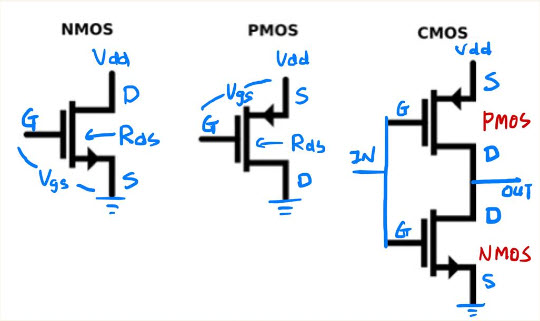
I often get confused with how NMOS or PMOS transistors output the logic “0” and “1”. One misconception I had is that I thought when NMOS or PMOS is in an “off” state, there should be an output. However, I missed an important fact that for a gate to transmit a clear output, the circuit must be able to conduct between Drain and Source. And it is in this sense that the resistance between D and S, the Rds, and the Ohm’s Law of electrical circuits helps me understand the case.

For NMOS, when Vgs is positive (as an input of logic “1”), the circuit becomes conductive. As the Rds becomes very low and essentially pulls the output (Drain) to the voltage close to ground, it transmits a clear logic “0”. When Vgs is zero or negative (as an input of logic “0”), the circuit becomes non-conductive, resulting in a high resistant Rds. Therefore, the voltage on output (Drain) becomes undefined, depending on the rest of the circuit that D is connected with.

On the other hand, for PMOS, when Vgs is negative (as an input of logic “0”), the circuit becomes conductive. As the Rds becomes very low and essentially pulls the output (Drain) to the voltage close to Vdd, it transmits a clear logic “1”. When Vgs is zero or positive (as an input of logic “1”), the circuit becomes non-conductive, resulting in a high resistant Rds. This causes the voltage on output (Drain) to become undefined, which, similar to NMOS, depends on the rest of the circuit that D is connected with.

By combining both PMOS and NMOS together as a CMOS, a clear output (Drain) of “0” or “1” can be transmitted with accordance to the signal from the input (Gate). This can be clearly shown in the NOT gate in the picture below.